HOTLINE: +840902720814

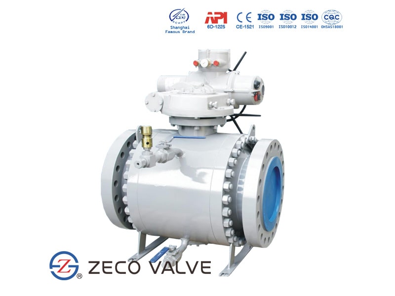
Ball valves can be combined with a electric actuator (motorized ball valves) for automation and/or for controlling remotely.
The working of an motorized ball valve is similar to its manual counterpart but in this valve, an electric actuator is mounted instead of a lever to drive the stem (which is connected to the ball) which in turn, rotates the ball to provide the desired operation. As the electric actuator receives a signal from remote control location depending on its position it will rotate to start or stop the flow of fluid through the ball valve.
An motorized ball valve can be designed to change positions based on sensor readings. A sensor can detect and report changes in temperature or pressure. The motorized ball valve is triggered when the sensor reaches a predetermined point set by machine management staff. This could perform important functions, such as keeping more process fluid from reaching an area that is already full. When the sensor detects that the area is available for more fluid, it activates the motorized ball valve, which changes position to allow process fluid to reach that location.
Motorized ball valves is mainly composed of two parts, namely electric actuator and valve. After certain installation and debugging, the switch of the equipment can be adjusted and controlled normally. The motorized ball valves mainly relies on the motor to drive and execute the operation, the size of the opening can also be adjusted according to the actual situation, so as to control the flow of equipment intermediary, is a very humane operating system.
Motorized ball valves can be switched from open to fully closed without any stops at any position in between. Every time the actuated ball valve finishes the cycle of opening and closing, the electric motor will switch off through internal cams, which strikes the limit switches.
For instance, when the electric motor receives a signal of closing the motorized ball valve, the motor is energized, rotating in order to close the ball valves. Subsequently, the limit switches travel on the cam as the internal cam rotates on the shaft until the lobe makes the switch to stop the electric motor, breaking the circuit.
Another type of application requires the motorized ball valves to open or close partially, detecting and responding to the various conditions of water flows. In this case, the goal can be achieved through the incorporation of a digital position sensor.
Depending on the special flow requirements, the external control command signal will be created. This input signal will be compared by the actuator of the motorized ball valves consistently to the actual position through the output feedback element. Subsequently, the actuated ball valves will be driven to balance the commands and reach the required position. A signal of approximately 4mA or 0V is typically used to close the motorized ball valves.
Motorized ball valves introduce into the systems to control valve opening and closing. To measure flow, they are often equipped with gauge monitors or flow meters. Industrial processes, manufacturing factories, chemical handling, food, and beverage equipment, mining operations, power plants, and the energy sector uses actuated ball valves. They’re also used in wastewater treatment, municipal treatment centres, clean water generation, aquariums, aquatics and animal care, chemical production, metals and plating operations, and chemical synthesis.
| No | Part | Material |
| 1 | Body | ASTM A105 |
| 2 | Bonnet | ASTM A105 |
| 3 | Ball | ASTM A182 F316 |
| 4 | Seat | ASTM A182 F316 + NYLON |
| 5 | Stem | ASTM A276 316 |
| 6 | Anti-static Device | SS316 |
| 7 | Gasket | Graphite + SS316 |
| 8 | Bolt | ASTM A193 B7 |
| 9 | Nut | ASTM A194 2H |
| 10 | O-ring | Viton A |
| 11 | Motorized Actuator | Aluminium |

Nhập email của bạn để nhận thông báo sớm nhất của chúng tôi
