HOTLINE: +840902720814

In the world of valves, ball valves are known for their compact, durable design and reliable, fast-acting on/off control. Ball valves utilize a ball with a hole (known as a port) drilled through the center to control the flow of media. The ball is rotated 90 degrees to align the port with the valve body and allow media to flow through the valve. To close the valve, the ball is rotated 90 degrees back to the closed position. All ball valves rely on the use of two seats, usually made of polytetrafluoroethylene (PTFE), to hold the ball in place and create a tight seal to prevent media from leaking through the valve.
Floating and trunnion are two basic types of ball valve designs.
Floating ball valves are the most common type of valve used in industrial piping systems. These valves are designed so that as the seats begin to wear the pressure from the media flowing through the valve will force the ball against the downstream seat to maintain a tight seal.
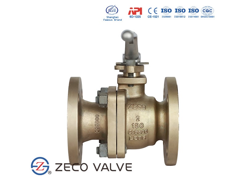
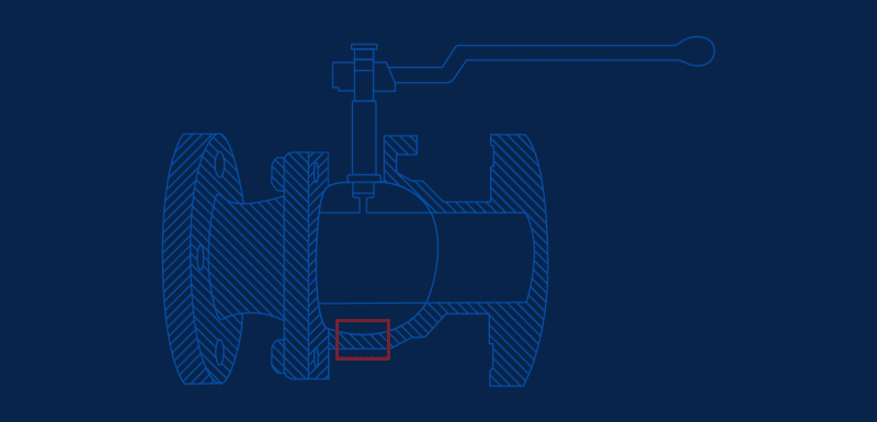
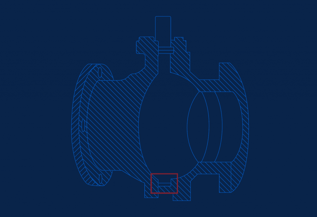
ZECO floating ball valve has two seats supporting the ball. Under medium pressure, the ball can be pressed tightly to the sealing surface for sealing at the outlet end.
In floating ball valves, the ball is pushed against the downstream seat by the in-line pressure, resulting in tightness.

In trunnion ball valves, the ball is fixed in place by bearings that prohibit it from floating downstream. A spring-loaded seat mechanism ensures that the valve remains leak-tight as the seat inevitably begins to wear down.

The shaft of floating ball valve is connected at the top of the ball and allows the switch from an open to a closed position with a quarter turn movement (90 degrees). When the shaft is moved, a load is applied to the ball which gets pressed against its seats.
When operated from closed to open position, the ball is to be rotated against both the in-line pressure (∆p) and the friction of the seats. In other words: the torque needed to operate the valve is created by both in-line pressure and the nature of the valve seats. The amount of torque required increases significantly when operating pressure (∆p) and/or valve size increase, and/or whenever the nature of the seat is made more robust. The latter applies in the case of a metal seated valve design.
This design, which is lightweight and economic, suits bore sizes up to 10 inches: above this bore size, the seats of the valve would not be able to withstand heavier and heavier balls and the valve would not operate safely and efficiently.
| Design | API 6D, API 6DSS, ASME B16.34, ISO 14313, ISO 17292 |
| Design pressure | ASME B16.34, EN 1092-1, ISO 17292 |
| Body wall thickness | ASME B16.34, ASME VIII Div. I, ISO 17292 |
| Face to Face | API 6D, ASME B16.10 Long pattern |
| Temperature range | -50° to 200°C (-58° to 392°F) |
| Pressures range | PN10 (ANSI 150) to PN420 (ANSI 2500) |
| Size range | DN15 (1/2″) to DN250 (10″) |
| End connections | ASME B16.5 Flanged RF, FF, RTJ ASME B16.25 Butt-Weld BW ASME B16.11 Socket-Weld SW ASME B36.10 Plain-End PE ASME B1.20.1 Threaded NPT (F/M) |
| No | Part | Material |
| 1 | Body | ASTM A216 WCB |
| 2 | Bonnet | ASTM A216 WCB |
| 3 | Ball | ASTM A105 |
| 4 | Seat | ASTM A105 + PTFE |
| 5 | Stem | ASTM A182 F6a |
| 6 | Anti-static Device | SS304 |
| 7 | Gasket | Graphite + SS304 |
| 8 | Bolt | ASTM A193 B7 |
| 9 | Nut | ASTM A194 2H |
| 10 | O-ring | Viton A |
| 11 | Lever | ASTM A216 WCB |

Nhập email của bạn để nhận thông báo sớm nhất của chúng tôi
